Rendering Volumetric Fog Using Custom URP Render Pass
Overview
For some time now I have been meaning to create a ramble showing how to make use of scriptable render passes in the Unity Universal Render Pipeline (URP). There is a plethora of use-cases for custom passes, but I needed a topic that would be widely applicable to most applications. Then last month I found myself taking a second pass at implementing fog. A true volumetric raymarched fog, as opposed to the traditional depth-based implementation.
And here we are now. In this ramble I will cover two topics: custom render passes and volumetric fog. The former is accomplished using C# and the latter is (mostly) implemented using HLSL.
To accomplish volumetric fog we will,
- Setup a custom render feature and render pass.
- Create a
FogVolumecomponent which provides the position and general features of fog. - Within our pass render each volume using our
VolumetricFogshader to an offscreen render texture. - Blend that offscreen texture onto our camera.
This is all done after rendering our opaque and transparent objects, but before any other post-processing effect.
As this is a fairly lengthy ramble, feel free to explore the sample repository as you read it.
Note: This article assumes a working, if basic, knowledge of raymarching. If you are unfamiliar with the technqiue I suggest visting some of these other sources first.
Custom Render Passes
Custom render passes are a powerful URP feature that allow you to execute arbitrary draw commands using the in-game cameras. These can draw onto the current camera buffers, off-screen render targets, or both. At this time I am currently making use of 16 passes in my current project for things such as:
- Rendering volumetric clouds and fog
- Capturing depth of transparent objects
- Capturing world-y of terrain around the camera
- Rendering outlines
Each pass is actually composed of three different objects:
- Feature implementing
ScriptableRendererFeature - Pass implementing
ScriptableRenderPass - Settings which is an arbitrary class
Scriptable Render Feature
The render feature is responsible for instantiating your pass and assigning it to the appropriate camera(s).
using UnityEngine;
using UnityEngine.Rendering.Universal;

namespace VertexFragment
{
    public sealed class VolumetricFogFeature : ScriptableRendererFeature
    {
        public VolumetricFogSettings Settings = new VolumetricFogSettings();
        private VolumetricFogPass Pass;

        public override void Create()
        {
            Pass = new VolumetricFogPass(Settings);
        }

        public override void AddRenderPasses(ScriptableRenderer renderer, ref RenderingData renderingData)
        {
            if (renderingData.cameraData.camera != Camera.main)
            {
                return;
            }

            renderer.EnqueuePass(Pass);
        }

        [System.Serializable]
        public sealed class VolumetricFogSettings
        {
            public RenderPassEvent Event = RenderPassEvent.BeforeRenderingPostProcessing;
            public Material VolumetricFogMaterial;
            public bool InstantiateMaterial;
        }
    }
}
It is added to the Universal Render Data asset assigned to your Universal Render Pipeline asset. Typically there is one pipeline asset for each quality level baked into your application. These are, by default, located under Assets/Settings.

In this asset new features can be added, ordered, and their settings configured. Having multiple different renderer data assets allows you to also assign only specific features to certain cameras. For example, if you have a secondary camera responsible for capturing top-down orthographic views (for minimaps, height data, etc.) then you do not need to also assign cloud rendering, outlines, etc. to it.
Scriptable Render Pass
Inside the render pass is where all of your custom rendering is performed.
There are two primary methods to implement within your custom pass: OnCameraSetup and Execute. The first provides you with a CommandBuffer and RenderingData which can be used to clear and resize (if needed) your render targets. The latter gives you a ScriptableRenderContext and is where you queue up the rendering operations.
Other virtual methods are available to implement, as well as numerous utility functions intended to help queue up common rendering tasks such as blitting. The official documentation can be found here which covers these in some detail.
I believe the best way to learn how to use a custom pass is to see a working example. This next section will explore the pass used to render the volumetric fog, which is effectively the C# side of the effect. The shader itself will be explored in the Volumetric Fog section.
Volumetric Fog Render Pass
The general structure of the VolumetricFogPass is:
public sealed class VolumetricFogPass : ScriptableRenderPass
{
    private static readonly List<FogVolume> FogVolumes = new List<FogVolume>();
    private static bool ShouldRender;

    private Material FogMaterialInstance;
    private MaterialPropertyBlock FogMaterialProperties;
    private BufferedRenderTargetReference BufferedFogRenderTarget;

    public VolumetricFogPass(VolumetricFogFeature.VolumetricFogSettings settings) { /* ... */ }

    public override void OnCameraSetup(CommandBuffer commandBuffer, ref RenderingData renderingData) { /* ... */ }
    public override void Execute(ScriptableRenderContext context, ref RenderingData renderingData) { /* ... */ }

    public static void AddFogVolume(FogVolume volume) { /* ... */ }
    public static void RemoveFogVolume(FogVolume volume) { /* ... */ }
}
We will explore each of these in depth below.
But before we dive into the pass I want to note that there are several custom classes/methods used:
- RenderTargetReference
- BufferedRenderTargetReference
- HasCameraResized
- RasterizeColorToTarget
- BlitBlendOntoCamera
While these will be glossed over in this article, they can be explored in the sample repository. Hopefully their names are clear enough so that you can still easily follow along when they appear.
Tracked Fog Volumes
The goal of our volumetric fog is to be able to define and place volumes throughout the world. This is accomplished via a FogVolume component that can be attached to any GameObject. This volume defines the center and bounds in which the fog exists and must be registered with the render pass in order to be drawn.
public sealed class FogVolume : UOPBehaviour
{
    public float Radius = 100.0f;

    // ... all of the other properties ...

    private void Start()
    {
        VolumetricFogPass.AddFogVolume(this);
    }

    private void OnDestroy()
    {
        VolumetricFogPass.RemoveFogVolume(this);
    }

    public void Apply(MaterialPropertyBlock propertyBlock)
    {
        // ... apply all of the properties during the render pass ...
    }
}
Which call into our static pass methods:
public static void AddFogVolume(FogVolume volume)
{
    RemoveFogVolume(volume);
    FogVolumes.Add(volume);
}

public static void RemoveFogVolume(FogVolume volume)
{
    FogVolumes.RemoveAll(f => f == volume);
}
Initialization
Once we have a FogVolume present in the world, we can move onto initializing our render pass. Pass initialization can be thought of occuring in two stages: once per application lifecycle and once per frame. The per-application initialization occurs within the constructor.
private static readonly List<FogVolume> FogVolumes = new List<FogVolume>();
private static readonly Color ColorNothing = new Color(0, 0, 0, 0);
private static bool ShouldRender;

private Material FogMaterialInstance;
private MaterialPropertyBlock FogMaterialProperties;
private BufferedRenderTargetReference BufferedFogRenderTarget;

public VolumetricFogPass(VolumetricFogFeature.VolumetricFogSettings settings)
{
    renderPassEvent = settings.Event;
    FogMaterialInstance = GameObject.Instantiate(settings.VolumetricFogMaterial);
    FogMaterialProperties = new MaterialPropertyBlock();
    BufferedFogRenderTarget = null;
}
This is all fairly straightforward.
renderPassEventis a member of the parentScriptableRenderPassclass which specifies where in the render pipeline our pass should be executed.FogMaterialInstanceis an instantiation of our material/shader used to draw the volumetric fog.FogMaterialPropertiesare the per-volume input properties to our volumetric fog.BufferedFogRenderTargetis our double-buffered offscreen render target that we render the fog directly onto (which is then blended onto the camera buffer).
FogMaterialInstance.SetVector(ShaderIds.BoundingSphere, boundingSphere);However, it is important to remember that the rendering done in a custom pass is accomplished using commander buffers. A command buffer simply represents a queue of commands to issue to the GPU and do not necessarily occur when you invoke them.
As these command buffers may be executed asynchronously from your C# code, a call to your material may update it out of sync with when the GPU command is actually issued. Instead you make use of a MaterialPropertyBlock.
When you use a command buffer with a MaterialPropertyBlock it makes a copy of the block so that when it does eventually issue the GPU command the properties are preserved as of the time of your invocation.
With the pass itself instatiated, your other inherited methods will now be called each frame for each camera it is assigned to. The first of these is the OnCameraSetup. Within this method nothing needs to be done, but it is a good place to perform your buffer clears and optional resizes. These could all be done within the Execute method, but it is nice to keep everything logically separated. If you plan on rendering fog to multiple cameras, and they are not all the same dimensions, it would be more performant to use a separate buffer for each camera instead of repeatedly resizing.
public override void OnCameraSetup(CommandBuffer commandBuffer, ref RenderingData renderingData)
{
    ShouldRender = FogVolumes.Exists(f => f.gameObject.activeInHierarchy);

    if (!ShouldRender)
    {
        return;
    }

    if (HasCameraResized(ref renderingData))
    {
        BufferedFogRenderTarget = BufferedFogRenderTarget ?? new BufferedRenderTargetReference("_BufferedVolumetricFogRenderTarget");
        BufferedFogRenderTarget.SetRenderTextureDescriptor(new RenderTextureDescriptor(
            renderingData.cameraData.cameraTargetDescriptor.width / 2,
            renderingData.cameraData.cameraTargetDescriptor.height / 2,
            RenderTextureFormat.ARGB32, 0, 1), FilterMode.Bilinear, TextureWrapMode.Clamp);
    }

    BufferedFogRenderTarget.Clear(commandBuffer, ColorNothing);
    FogMaterialProperties.SetMatrix(ShaderIds.CameraNearPlaneCorners, renderingData.cameraData.camera.GetNearClipPlaneCornersMatrix());
}
First we check if there are any registered and active fog volumes, since if there aren’t we don’t need to carry on any further with camera setup or execution. Depending on scene complexity, expected volume counts, etc. it may be beneficial to also perform basic frustum culling on the volumes.
We next move onto instantiating and/or resizing our fog render target. Note that we are drawing to a quarter-sized buffer, as compared to the main camera buffer, which means we only have to render a 16th of the fragments each frame. This is the same technique I explore in the Upsampling to Improve Cloud Render Performance ramble. Depending on your hardware targets, scene complexity, artistic direction, etc. you may be able to get away with rendering the fog to an even smaller buffer. As fog tends to be a fairly low-key effect, and is naturally blurry/indistinct, it can get away with a “lower” quality level compared to other effects.
Next we clear away our back buffer in preparation for the upcoming render. Note that we clear to “nothing” instead of black so that the alpha channel is also zeroed out.
The final line is key to performing accurate screen-space raymarches. In it we pack the world-space corners of our near-clip plane into a matrix which is then used in the shader. In my experience, any other approach to getting ray origins is less accurate and can suffer from severe distortion depending on the camera angle. This will be discussed in more detail when we go over the vertex shader.
Execution
With everything setup we can move onto our Execute method which issues the commands to draw and blend the fog.
public override void Execute(ScriptableRenderContext context, ref RenderingData renderingData)
{
    if (!ShouldRender)
    {
        return;
    }

    CommandBuffer commandBuffer = CommandBufferPool.Get("VolumetricFogPass");

    using (new ProfilingScope(commandBuffer, new ProfilingSampler("VolumetricFogPass")))
    {
        // ... draw commands
    }

    context.ExecuteCommandBuffer(commandBuffer);
    commandBuffer.Clear();

    CommandBufferPool.Release(commandBuffer);
}
Essentially all Execute implementations will have this same general structure:
- Check if we should do anything (
ShouldRenderset earlier inOnCameraSetup) - Request a command buffer and begin profiling (one is not explicitly provided)
- Issue the drawing commands to the command buffer.
- Execute the buffer and cleanup.
It is the third step that will generally change between different rendering passes.
For volumetric fog the issued commands are simple:
- For each fog volume, render it onto the shared back buffer setup in
OnCameraSetup. - Once each volume has been drawn, blend it onto the camera color buffer.
foreach (var fogVolume in FogVolumes)
{
    if (!fogVolume.gameObject.activeInHierarchy)
    {
        continue;
    }

    fogVolume.Apply(FogMaterialProperties);
    RasterizeColorToTarget(commandBuffer, BufferedFogRenderTarget.BackBuffer.Handle, FogMaterialInstance, BlitGeometry.Quad, 0, FogMaterialProperties);
}

BlitBlendOntoCamera(commandBuffer, BufferedFogRenderTarget.BackBuffer.Handle, ref renderingData);
RasterizeColorToTarget blits onto the target buffer using a full-screen quad. While the built-in ScriptableRenderPass parent class of our custom pass does provide a Blit method, that method does not take in a MaterialPropertyBlock. The only way to modify properties when invoking Blit is to use the material itself, which means you can not change properties mid-pass unless you maintain multiple instances of the same material.
This is not ideal, hence the existence of RasterizeColorToTarget which does take a MaterialPropertyBlock and instead of using Blit it uses the DrawMesh method of the provided command buffer.
BlitBlendOntoCamera uses Blit, since it is called only once per pass, with the custom BitBlend.shader derived material to blend our cumulative fog buffer onto the camera color buffer.
When to use Blit vs CommandBuffer.DrawMesh vs some other approach can be confusing when first writing custom render passes and is something that took me some time to get used to. Especially since, at least in my case, I would only write a few passes each year. Just long enough between them to keep forgetting the fine details. Of course you could go without the Blit convenience method entirely and rely only on DrawMesh. Maybe I should do that …
Until of course someone comes along and tells me exactly why I shouldn’t have done that and I find myself undoing those changes. Anyways, onto the fun part!
Volumetric Fog
At this point the C# infrastructure is in place and we can move onto implementing the shader.
From a high-level the effect is simple. For each fragment we will,
- Perform a raycast (or two) to determine if we hit our fog volume. If we missed, we exit the shader.
- Use the double raycast to know (A) where we hit and (B) the distance until we leave the volume.
- Raymarch through the volume, accumulating fog density (particulates) and lighting information.
- Calculate a final lighting and color value (including opacity) from our accumulated data.
Vertex Shader
While for most screen-space effects the vertex shader is more-or-less a simple pass through, there is an additional step that we need to take for accurate raycasts/raymarching in the fragment shader. Typically, for a screen-space effect we can calculate the ray direction as follows:
float3 GetRayDirection(float2 screenUV)
{
    float3 right = UNITY_MATRIX_V._m00_m01_m02;
    float3 up = UNITY_MATRIX_V._m10_m11_m12;
    float3 forward = -UNITY_MATRIX_V._m20_m21_m22;

    float2 uv = (screenUV * 2.0f) - 1.0f;
    uv.x *= (_ScreenParams.x / _ScreenParams.y);

    return normalize((uv.x * right) + (uv.y * up) + (forward * 2.0f));
}
This works great for many effects, and especially for demos like on ShaderToy. However, this approach does distort the ray direction at the screen edges, which may not be noticeable in a fixed (or controlled) demo, but becomes apparent when the user has full control of the camera. This is because the forward component is a constant term, whereas the influence from the right and up vectors increases as you move away from the screen center. This is the difference between a rounded and flat frustum, which is visibly demonstrated here.

There are surely many solutions to this problem, but one that I prefer makes use of the near plane corners as it is conceptually very simple. For a full-screen quad blit we can map each corner of the screen, or the target buffer, to a specific quad vertex. These vertices also map to corners of the view frustum, specifically both the near and far-clip planes. If we assign to each vertex the world-space position of its corresponding near-plane corner, we can then retrieve the interpolated position in the fragment shader. By then subtracting the camera position from our fragment near-plane position, we have a vector extending from the camera to the near plane. Simply normalize that and we have a more accurate ray direction which does not suffer from a constant-term forward vector.
float4x4 _CameraNearPlaneCorners;
float4x4 _CameraFarPlaneCorners;

#define CAMERA_NEAR_PLANE_UL _CameraNearPlaneCorners._11_21_31
#define CAMERA_NEAR_PLANE_UR _CameraNearPlaneCorners._12_22_32
#define CAMERA_NEAR_PLANE_LL _CameraNearPlaneCorners._13_23_33
#define CAMERA_NEAR_PLANE_LR _CameraNearPlaneCorners._14_24_34

float3 SampleBilinear3(float u, float v, float3 ul, float3 ur, float3 ll, float3 lr)
{
    return ((1.0f - u) * (1.0f - v) * ll) +
            (u * (1.0f - v) * lr) +
            ((1.0f - u) * v * ul) +
            (u * v * ur);
}

float3 GetNearPlaneWorldSpacePosition(float u, float v)
{
    return SampleBilinear3(u, v, CAMERA_NEAR_PLANE_UL, CAMERA_NEAR_PLANE_UR, CAMERA_NEAR_PLANE_LL, CAMERA_NEAR_PLANE_LR);
}

VertOutput VertMain(VertInput input)
{
    VertOutput output = (VertOutput)0;

    output.position = float4(input.position.xyz, 1.0f);
    output.positionWS = GetNearPlaneWorldSpacePosition(input.uv.x, input.uv.y);     // World-space on the near plane
    output.uv = input.uv;

    return output;
}

float4 FragMain(VertOutput input) : SV_Target
{
    float3 rayOrigin = input.positionWS;
    float3 rayDirection = GetRayDirectionnormalize(rayOrigin - _WorldSpaceCameraPos.xyz);

    // ...
}
Where _CameraNearPlaneCorners was passed in earlier in our OnCameraSetup.
Fragment Shader
At long last we can finally work on the actual volumetric fog. The fragment shader can be split into four distinct sections:
- Setup and Raycast
- Raymarch Preparation
- Raymarch and Accumulation
- Finalization
The entire processes can be summed up as: we raymarch through a volumetric sphere, and at each step we accumulate particulate density. The total amount of fog accumlated is used, along with lighting information, to determine the fog color and opacity.
As we cover each section, we will begin with the full code for that piece. That code will then be broken down line-by-line. Some helper functions may be passed over, but again the full source code can be found here.
Setup and Raycast

float4 FragMain(VertOutput input) : SV_Target
{
    // -------------------------------------------------------------------------
    // 1. Setup and Raycast
    // -------------------------------------------------------------------------

    float3 rayOrigin = input.positionWS;
    float3 rayDirection = normalize(rayOrigin - _WorldSpaceCameraPos.xyz);

    float3 sphereOrigin = _BoundingSphere.xyz;
    float sphereRadius = _BoundingSphere.w;

    float linearDepth = Linear01Depth(SampleSceneDepth(input.uv), _ZBufferParams);
    float worldDepth = LinearDepthToWorldDepth(linearDepth);

    RaySphereHit rayHit = GetRaySphereIntersectionData(rayOrigin, rayDirection, sphereOrigin, sphereRadius);
    float hitOcclusionFlag = step(rayHit.FrontHitDistance, worldDepth);

    if (hitOcclusionFlag <= 0.0f)
    {
        return (float4)0;
    }

    return float4(0.0f, 0.0f, 0.0f, rayHit.Thickness01);
}
We start by defining our rayOrigin and rayDirection, which we did the bulk of the work for in the vertex shader.
Next calculate the depth of the fragment in world-space using the linear depth sampled from the camera depth buffer. Retrieving the linear depth is accomplished with two built-in Unity functions: SampleSceneDepth and Linear01Depth. The linear depth, on the range [0, 1], can then be interpolated to world-space depth on the range [near clip, far clip].
float LinearDepthToWorldDepth(float linearDepth)
{
    return lerp(_ProjectionParams.y, _ProjectionParams.z, linearDepth);
}
Once we have the ray, sphere volume, and depth we can perform two raycasts. The first is from our ray origin along the positive ray direction, which gives the front of the volume, and then the second is from the opposite direction from a distance away, which gives the back of the volume. There are three different cases we have to consider when performings these casts:
- The first raycast, along
rayDirection, hits the volume and it is in front of us. - The first raycast “missed” because we are inside of it.
- The first raycast missed because we are outside of it.
If the first hits, that is when we perform the second cast along -rayDirection. If it misses, we are inside the volume if we are less than the radius around from the origin. To determine the volume thickness we just subtract the two hit points.
For the raycast, I use a modified version of the function presented in the article Raytracing - Ray Sphere Intersection. Among the various implementations of ray / sphere intersections floating around in my codebases, this is by far the simplest that also provides a hit distance.
float RaySphereIntersection(float3 ro, float3 rd, float3 so, float sr)
{
    float3 so2ro = ro - so;

    float a = 2.0f * dot(so2ro, rd);
    float b = dot(so2ro, so2ro) - (sr * sr);
    float c = (a * a) - (4.0f * b);

    float hitFlag = step(0.0f, c);
    float hitDistance = (-a - sqrt(c)) * 0.5f;

    return (hitDistance * hitFlag);
}
The double-raycast is implemented in GetRaySphereIntersectionData:
struct RaySphereHit
{
    float Hit;
    float FrontHitDistance;
    float3 FrontHitPoint;
    float3 BackHitPoint;
    float Thickness;
    float Thickness01;
};

RaySphereHit GetRaySphereIntersectionData(float3 rayOrigin, float3 rayDirection, float3 sphereOrigin, float sphereRadius)
{
    RaySphereHit hit = (RaySphereHit)0;
    hit.FrontHitDistance = RaySphereIntersection(rayOrigin, rayDirection, sphereOrigin, sphereRadius);
    hit.Hit = step(0.0f, hit.FrontHitDistance);

    float sphereDiameter = sphereRadius * 2.0f;

    // The ray hit twice, so the sphere is in front of us.
    if (hit.Hit > 0.0f)
    {
        float3 sphereBackRayOrigin = rayOrigin + (rayDirection * (hit.FrontHitDistance + (sphereRadius * 3.0f)));
        float sphereBackDistance = RaySphereIntersection(sphereBackRayOrigin, -rayDirection, sphereOrigin, sphereRadius);

        hit.FrontHitPoint = rayOrigin + (rayDirection * hit.FrontHitDistance);
        hit.BackHitPoint = sphereBackRayOrigin + (-rayDirection * sphereBackDistance);
        hit.Thickness = distance(hit.FrontHitPoint, hit.BackHitPoint);
        hit.Thickness01 = saturate(hit.Thickness / sphereDiameter);
    }
    // The ray did not hit. Either it is a miss or we are inside of the sphere.
    else
    {
        float distanceToSphere = distance(rayOrigin, sphereOrigin);

        // Are we inside of the sphere?
        if (distanceToSphere < sphereRadius)
        {
            float3 sphereBackRayOrigin = rayOrigin + (rayDirection * sphereDiameter);
            float sphereBackDistance = RaySphereIntersection(sphereBackRayOrigin, -rayDirection, sphereOrigin, sphereRadius);

            hit.FrontHitPoint = rayOrigin;
            hit.FrontHitDistance = 0.0f;
            hit.BackHitPoint = sphereBackRayOrigin + (-rayDirection * sphereBackDistance);
            hit.Thickness = distance(rayOrigin, hit.BackHitPoint);
            hit.Thickness01 = saturate(hit.Thickness / sphereDiameter);
        }
    }
    // Otherwise a miss.

    return hit;
}
There are likely some optimizations to be made here (use squared distances to avoid sqrt, is a second entire raycast needed if inside the sphere, etc.) but works well enough and has no performance issues on my 10 year old machine.
The result of GetRaySphereIntersectionData is the RaySphereHit structure which contains where the ray(s) hit and the thickness of the volume “remaining” along the ray on the range [0, 1] where 1 is the full diameter and 0 is no thickness left (on the extreme edge). The ray hit data is combined with our depth information to form the hitOcclusionFlag:
float hitOcclusionFlag = step(rayHit.FrontHitDistance, worldDepth);

if (hitOcclusionFlag <= 0.0f)
{
    return (float4)0;
}
Why is it defined as step(y, x) and not step(x, y)? It is implemented as:
return (x >= y) ? 1 : 0;So why would you take in y as the first parameter? Who does that?
This flag tells us two things: if we hit our sphere volume AND it is not occluded by another object in the scene. If either of these aren’t true (missed or blocked) then we early exit before we begin the raymarch.
Raymarch Preparation

The second section is the classic “time to initialize all of the miscellaneous variables we will need” block of code. This section can be further broken down into the following manageable chunks.
float occludedDistance = worldDepth - rayHit.FrontHitDistance;
float nearestCutoff = min(occludedDistance * 5.0f, rayHit.Thickness);
Here we determine just how far we will be marching from our point-of-entry in the volume. We either march until we exit the volume or until we hit an occluder, well a bit past an occluder. The * 5.0f just happens to be a value that seems to look the best. To paraphrase an old SpeedTree white paper, “the value was found through careful experimentation." Not to say there isn’t a reason for it, but we will get to that later.
int stepCount = 50;
float stepSize = nearestCutoff / (float)stepCount;

float3 currPosition = (float3)0;
float totalDistance = rayHit.FrontHitDistance;
float distanceMarched = Hash13(rayOrigin * 1337.0f * sin(_Time.y)) * -stepSize * 0.1f;
This prepares our marcher with how far each step will be and where the march should begin at. A couple things to note:
- A linear step size is used. Other implementations, such as the one described in the article “Volumetric Fog and Lighting” in GPU Pro 6, make use of a non-linear step. However, I found this wasn’t needed to accomplish my goals.
- The starting position is offset slightly by a random amount to reduce banding artifacts as described in this ramble.
Light light = GetMainLight();
float dotRaySun = pow(saturate(dot(rayDirection, light.direction)), _DirectionalFallExponent);
float3 lightColor = lerp(lerp((float3)1, light.color, _LightContribution), lerp((float3)1, light.color, _DirectionalLightContribution), dotRaySun);
float4 fogColor = lerp(_FogColor, _DirectionalFogColor, dotRaySun);
The primary directional light is fetched, and with it we calculate our light and fog color. Both of these are influenced by the angle of our ray to the light source, and we have variables exposed precisely for this purpose. This allows us to have the light and fog be tinted differently, say more orange, if the ray is running towards the light source.
float edgeFadeStart = sphereRadius - _FogFadeEdge;
float yFadeStart = _FogMaxY - _FogFadeY;
These are used to allow for a gradient at the edges of the volume and to avoid sharp, harsh lines when it ends.
And now we can move on to the actual marching.
Raymarch and Accumulation
While marching through our volume we will be accumulating particulate density and shadows.
float accumulation = 0.0f;
float shadowAccumulation = 0.0f;
Even though we are taking linearly sized steps through the volume, the step size can change. This will be explained shortly, but because of this we need a separate variable to store our current step size.
float currStepSize = stepSize;
int takingSmallSteps = 0;
Now we are finally ready to enter into the actual raymarch loop. Note the use of UNITY_LOOP which is an alias for the HLSL loop attribute. We are telling the compiler to leave our loop alone, and not to unroll it, as we have multiple texture samples and conditionals within it which make it hard (or impossible) for it to be properly unrolled.
UNITY_LOOP
for (int i = 0; i < stepCount; ++i)
{
    // 1. Step
    totalDistance += currStepSize;
    distanceMarched += currStepSize;
    currPosition = rayHit.FrontHitPoint + (rayDirection * distanceMarched);

    // 2. Fade
    float distToOrigin = distance(currPosition, sphereOrigin);
    float edgeFade = 1.0f - saturate((distToOrigin - edgeFadeStart) / _FogFadeEdge);
    float yFade = 1.0f - saturate((currPosition.y - yFadeStart) / _FogFadeY);
    float proximityFade = saturate(totalDistance / _FogProximityFade);

    // 3. Fog Sample
    float3 fogUVW = (currPosition.xyz + (_FogSpeed.xyz * _Time.y)) * _FogTiling.xyz;
    float fog = pow(SAMPLE_TEXTURE3D(_NoiseTexture, sampler_NoiseTexture, fogUVW).r, _FogExponent);
    fog = saturate((fog - _FogCutOff ) / (1.0f - fog));

    float3 detailFogUVW = (currPosition.xyz + (_FogSpeed.xyz * _DetailFogSpeedModifier * _Time.y)) * _DetailFogTiling.xyz;
    float4 fogDetail = pow(SAMPLE_TEXTURE3D(_NoiseTexture, sampler_NoiseTexture, detailFogUVW), _DetailFogExponent);
    fog = (fog * (1.0f - _FogDetailStrength)) + (_FogDetailStrength * ((fogDetail.r * 0.6f) + (fogDetail.b * 0.25f) + (fogDetail.a * 0.15f)));

    // 4. Step Back
    if (fog > 0.1f && takingSmallSteps < 1)
    {
        currStepSize = stepSize * 0.2f;
        distanceMarched -= currStepSize * 4.0f;
        takingSmallSteps = 1;
        continue;
    }

    // 5. Shadow Sample
    float shadow = MainLightShadow(TransformWorldToShadowCoord(currPosition), currPosition, 1.0f, _MainLightOcclusionProbes);

    // 6. Accumulation
    fog *= yFade * edgeFade * proximityFade;
    accumulation += fog * currStepSize;
    shadowAccumulation += currStepSize - (shadow * currStepSize);
}
That’s a big chunk of code, so let’s break it apart.
totalDistance += currStepSize;
distanceMarched += currStepSize;
currPosition = rayHit.FrontHitPoint + (rayDirection * distanceMarched);
We start with our basic stepping of the ray, the marching. Note the similar, but not identical, variables of totalDistance and distanceMarched. The former represents how far away from the ray origin (camera) that we are, and is used for proximity fading, and the latter is how far we have marched through the volume so far. These values will be nearly identical if the camera is inside the volume, though not identical due to the random starting offset done earlier.
float distToOrigin = distance(currPosition, sphereOrigin);
float edgeFade = 1.0f - saturate((distToOrigin - edgeFadeStart) / _FogFadeEdge);
float yFade = 1.0f - saturate((currPosition.y - yFadeStart) / _FogFadeY);
float proximityFade = saturate(totalDistance / _FogProximityFade);
Next we calculate our three different fade values:
edgeFade: fades along all the edges of the sphere volume.yFade: fades along a vertical gradient.proximityFade: fades depending on proximity to the camera.
Looking back at that now, that’s a lot of divisions. We could probably store those reciprocals outside of the loop …
float3 fogUVW = (currPosition.xyz + (_FogSpeed.xyz * _Time.y)) * _FogTiling.xyz;
float fog = pow(SAMPLE_TEXTURE3D(_NoiseTexture, sampler_NoiseTexture, fogUVW).r, _FogExponent);
fog = saturate((fog - _FogCutOff ) / (1.0f - fog));
float3 detailFogUVW = (currPosition.xyz + (_FogSpeed.xyz * _DetailFogSpeedModifier * _Time.y)) * _DetailFogTiling.xyz;
float4 fogDetail = pow(SAMPLE_TEXTURE3D(_NoiseTexture, sampler_NoiseTexture, detailFogUVW), _DetailFogExponent);
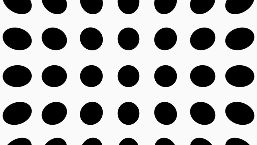
fog = (fog * (1.0f - _FogDetailStrength)) + (_FogDetailStrength * ((fogDetail.r * 0.6f) + (fogDetail.b * 0.25f) + (fogDetail.a * 0.15f)));Here is the key to the volumetric fog and the part that makes it actually volumetric: double sampling a 3D noise volume. The texture packs 4 different noise volumes into one, with a different noise in each channel. Which makes it actually a 6D noise. Maybe? I am not a mathematician.
.ra simplex noise.ga low-scale worley noise.ba medium-scale worley noise.aa high-scale worley noise
I think. It has been a while since I generated that texture …
Either way it is the secret sauce, and even if you had the full shader source code it would be useless without an appropriate noise texture to go with it. We sample this texture twice, at two different tiling scales and speeds.
- First sample is to get the general “shape” of the fog.
- Second sample is to get the details of the fog.
So the first gives us the billowing clouds of fog, while the second provides us with the finer mists that float by. It should be noted that the details are not adequately captured in screenshots and must be seen in motion to appreciate them. A visualization of this texture is shown below, and you can see the different noises present in each color channel.

CloudVolume64. This is infact the same texture I use for rendering volumetric clouds which have been featured in a few different rambles.
Generating a tileable 3D noise, especially one composed of multiple different noises, is it’s own challege and one I should probably ramble on about at some point.
if (fog > 0.1f && takingSmallSteps < 1)
{
    currStepSize = stepSize * 0.2f;
    distanceMarched -= currStepSize * 4.0f;
    takingSmallSteps = 1;
    continue;
}
This block performs a “step back and take smaller steps” logic switch in the loop. It is essentially the same thing that I call Adaptive Stepping and describe in this ramble. It is also discussed in the “The Real-Time Volumetric Cloudscapes of Horizon Zero Dawn” presentation.
Except it never goes back to full size steps, which is intentional.
With cloud rendering we perform adapative stepping to reduce banding artifacts. However, it is done here because what we are really concerned about with fog is the fog that is nearer to the camera. Without adapative stepping we would be accumulating far away fog drifts with the same priority as nearby ones. It is hard to describe the visual result of this other than it looks wrong as areas far away have full definition and areas nearby that don’t have fog further along the ray are undersampled and look faint.
float shadow = MainLightShadow(TransformWorldToShadowCoord(currPosition), currPosition, 1.0f, _MainLightOcclusionProbes);A simple sampling of the shadow from the primary light for our current position.
fog *= yFade * edgeFade * proximityFade;
accumulation += fog * currStepSize;
shadowAccumulation += (1.0f - shadow) * currStepSize;
We modify our fog by the various fade values calculated earlier in the loop, and then add the amount of fog over the last step to our ongoing accumulation total. The accumulation variable is increased by the average density over the step size.
The same is done for the shadow, except it is inversed as a shadow value of 0 is complete shadow and 1 is no shadow.
And that is it for the loop.
Finalization
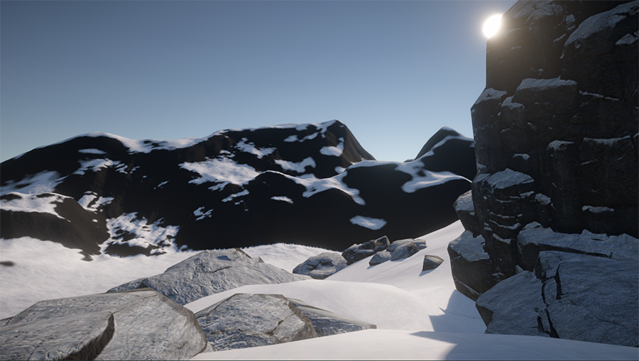
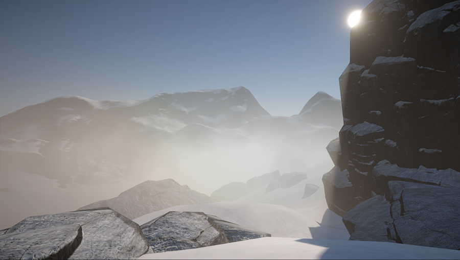
float totalAccumulation = saturate(accumulation / distanceMarched) * _FogDensity;We calculate a final totalAccumulation value which represents the relative fog density that we traversed along our ray. This is not a “realistic” fog accumulation, instead it is one that “looks” correct. What I mean by that is that in other implementations, such as the one described in the aforementioned “Volumetric Fog and Lighting” article, they define a relative particulate density and then that density is used directly.
Here in totalAccumulation I instead map it to a [0, 1] range which effectively represents “how much fog did we encounter out of the maximum amount of fog that we could have encountered?” I do this because originally this was also using a realistic approach, but it didn’t look right in certain edge cases even if it was correct.
For example, if the camera is at a raised position above the ground looking down, the user expects to see clouds of fog billowing below them. However, in a realistic accumulator the ray simply has not traversed through the medium enough to gather enough particulates to creates those clouds. So instead of seeing fog they just see the ground. Which is correct, but not what is visually expected.
By doing this mapping we do get those fog clouds below the camera. In order to achieve this with a realistic accumulator, the particulate density needs to be increased but then it develops density hotspots in the distance as shown in the image comparison at the top of this section. Our stylized accumulator results in an even density distribution across the scene.
float totalShadow = 1.0f - (saturate(shadowAccumulation / distanceMarched) * lerp(_ShadowStrength * _ShadowReverseStrength, _ShadowStrength, dotRaySun));
float3 totalLighting = lightColor * totalShadow;
float3 ambientLighting = lightColor * 0.1f;

return float4(fogColor.rgb * max(totalLighting, ambientLighting), fogColor.a * saturate(accumulation));
The last step is to calculate our lighting and apply it to our fogColor.
While we were marching we were accumulating shadows which is used to calculate totalShadow. This value is controlled by our _ShadowStrength and _ShadowReverseStrength input parameters. The higher these values are, the stronger and darker the resulting shadows on the fog will be. Typically we want to have a lower _ShadowReverseStrength as otherwise the shadows cast by objects into the fog can be cast for a very long distance, especially at low sun angles.
The lighting itself is very basic, simply multiplying our previously calculated lightColor with the totalShadow. As it uses lightColor, the totalLighting value is influenced by the angle of the ray to the primary light.
The .rgb of our final fog color is just fogColor * lighting, and the .a is the combination of the fog alpha and the amount accumulated by the marcher. And that’s it. After all of these words, it boils down to:
- Calculate
fogColor. - Calculate
lightColor. - Perform raymarching and accumulate particulates and shadow.
- Return
fogColor * lightColormodified by those accumulations.
Further Improvements
There are two features that I have planned for my volumetric fog, but have not yet been implemented at the time of writing this ramble. These are left for the reader to implement on their own as an exercise and may appear in the sample repository at a future date.
Arbitrary Volumes
The current implementation supports only spherical volumes, though there are multiple parameters which help shape it.
Ideally the volumes could be of arbitrary shapes, and this is something I have implemented, but not utilizied, for my traditional depth-based fog. To accomplish this, the FogVolume component should have a mesh assigned to it. Then in the custom render pass you perform the following steps prior to the fog rendering:
- Instantiate an additional render target.
- Render the front-face depth values of the volume mesh to the
.rchannel. - Render the back-face depth values of the volume mesh to the
.gchannel.
These depth values then give you the equivalent of the RayHit.FrontHitPoint and RayHit.BackHitPoint at the cost of a few extra, but cheap, renders.
Point Light Support
This is another feature present in my depth fog, but not in the volumetric, and is shown here.
In the depth fog this is done as part of the fog rendering, but for volumetric fog it needs to be an additional pass after the fog has been rendered, akin to a bloom effect. To achieve this I have another custom pass called LightSourceTexturePass which captures light sources (visualized with assigned meshes) to a buffer.
Initially I tried to support point lights in the raymarcher by gathering additional light sources each step, but this resulted in distant fog patches being lit the same as nearby ones as long as the ray passed through a light.
Source Code
 See the code on GitHub: https://github.com/ssell/UnityURPVolumetricFog
Written against:
- Unity v2023.2.1f1
Notes
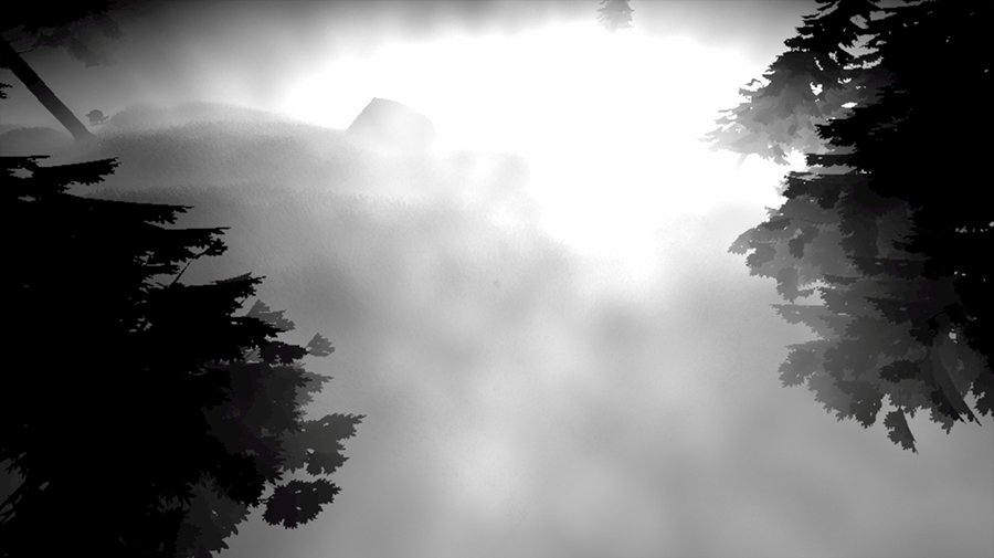
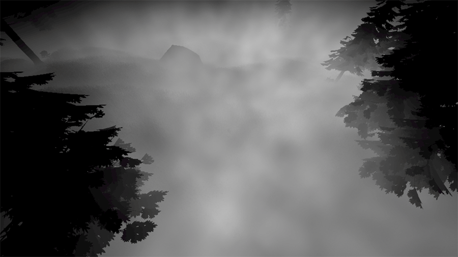
I was informed by my arctic contact that fog like shown in the header image and in the sample repository is unrealistic for cold climates. It instead becomes hoarfrost and the sky is clear. Living in Florida my whole life, I was not aware of this.
My counter-argument is as follows:
- It looks cool.
- A snowy mountain scene is faster to mock-up for a demo than a forest.